A solid foundation is the backbone of any journey, and our deep-cycle lithium battery guide lays that groundwork with care. We’ll discuss careful site selection, secure mounting, enclosure design, and robust wiring to ensure reliability and longevity. We’re outlining BMS integration, sensor placement, and proper fusing, while reminding you to plan ventilation and venting calculations. As we cover system layouts for campers, boats, and off-grid use, we’ll flag common pitfalls and what maintenance and monitoring entail—so you’re prepared to proceed with confidence, yet nothing is final until you’ve considered all the details.
Key Takeaways
- Plan proper mounting with vibration isolation, secure fasteners, ventilation, and compatibility with surrounding systems.
- size wiring with appropriate gauge, busbars, fusing, and clear main harness routing to minimize losses.
- Use a suitable BMS type (passive/active/integrated) matching balancing and protection needs.
- Ensure charger compatibility, correct CC/CV profile, temperature compensation, and safe termination voltages.
- Implement comprehensive safety and maintenance: venting, thermal management, sensor calibration, and regular monitoring.
What Is a Deep-Cycle Lithium Battery and When Should You Use It
What exactly is a deep-cycle lithium battery, and why should you consider using one? We define a deep-cycle lithium battery as a energy storage device designed for repeated, full or shallow discharge cycles with sustained capacity and efficiency. Unlike high-drip variants, it delivers consistent performance over long periods and withstands many charge–discharge cycles. You should consider one when you require reliable power for extended durations, reduced weight, and compact form factors. Applications include off-grid systems, recreational vehicles, and backup power. Key advantages include high energy density, fast charging, and low self-discharge. We emphasize proper sizing, thermal management, and safe handling. By choosing a sturdy deep cycle lithium battery, you gain long-term reliability, improved cycle life, and predictable performance for demanding energy demands.
Choose Chemistry and Capacity: A Practical Decision Framework
We examine battery chemistry options, weighing factors like energy density, cycle life, safety, and cost to guide your selection. We also establish capacity sizing principles that align with load profiles, desired autonomy, and charging constraints to prevent under- or over-sizing. Together, these considerations form a practical framework you can apply to balance performance, reliability, and value.
Battery Chemistry Considerations
Choosing the right battery chemistry and capacity is essential for reliability and cost efficiency in a deep cycle system. We evaluate chemistry options by performance, safety, and lifecycle costs, then align them with our load profile and charging regime. For lithium systems, we consider NMC, LFP, and blended chemistries, weighing energy density, cycle life, temperature tolerance, and risk factors. We emphasize internal protections, BMS features, and compatibility with our inverter and solar input. We assess safety testing requirements, including thermal behavior, short-circuit response, and overcharge protection, to ensure robust operation in field conditions. We also review available warranties, vendor support, and end-of-life handling to minimize total ownership costs. In this framework, clear criteria guide our final choice and documented justifications.
Capacity Sizing Principles
How do we translate load profiles into a practical battery size and chemistry choice that delivers reliable performance without waste? We approach capacity sizing by aligning our system’s nominal energy with expected usage and desired autonomy. We begin with a clear energy budgeting process: quantify daily and seasonal consumption, then select a chemistry that matches discharge and charge rates, cycle life, and efficiency targets. We factor derating for temperature, aging, and inverter losses, ensuring the chosen pack can sustain peak loads without excessive depth of discharge. We prioritize consistency between stated capacity and real-world performance, documenting assumptions and acceptance criteria. This framework emphasizes modularity, so追加 capacity can compensate for unplanned draws. Ultimately, our goal is to balance affordability, reliability, and longevity through disciplined capacity sizing.
Practical Decision Framework
To determine the right chemistry and capacity, we anchor decisions in documented load profiles and clear acceptance criteria established in capacity sizing. Our framework emphasizes verifiable inputs, quantified constraints, and objective trade-offs, ensuring selections align with mission-critical performance and lifecycle costs. We compare chemistries on energy density, cycle life, safety, and maintenance needs, then translate results into a capacity target that meets peak and average demands without overprovisioning. We also consider disposal considerations and environmental impact as part of the decision, ensuring responsible end-of-life planning is integrated from the outset. Financial analysis underpins risk-adjusted choices, presenting net present value, payback, and total cost of ownership for alternatives.
- Documented load profiles guide ranking and prioritization
- Quantified constraints ensure objective trade-offs
- End-of-life and cost implications drive final selection
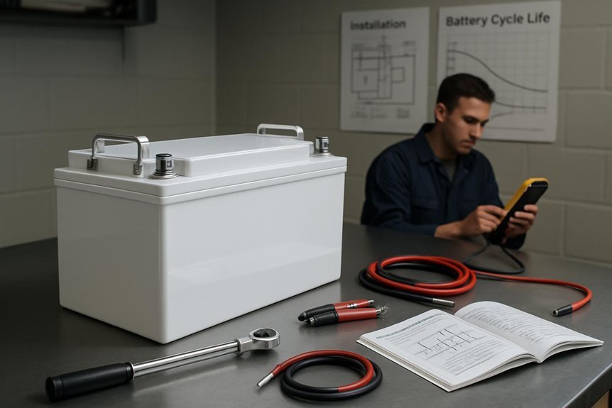
Plan Safe Mounting and Enclosure for Your Rig
We plan safe mounting and enclosure by outlining foundational mounting methods and enclosure considerations that minimize vibration, heat, and moisture exposure. We will address secure attachment, weight distribution, and accessibility for maintenance, while specifying weatherproof and flame-retardant enclosure options. By starting with these fundamentals, we invite you to evaluate your rig’s layout and ensure reliable, compliant operation.
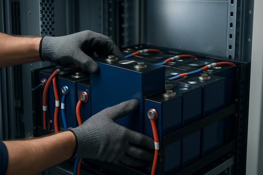
Safe Mounting Fundamentals
Choosing a safe mounting plan and enclosure is essential to protect both the battery system and surrounding components. We approach mounting with methodical planning, ensuring mechanical integrity, vibration damping, and accessibility for maintenance. Proper fasteners, strain relief, and thermal paths prevent fatigue and overheating, while isolation from incompatible systems reduces risk. We evaluate weight distribution, airflow, and drainage to avert moisture buildup. Documentation of criteria, installation steps, and inspection routines keeps the process reproducible and verifiable. During setup, we avoid irrelevant topic distractions and address stray notes only when they affect safety or performance. Regular inspections verify mounting alignment, fastener torque, and enclosure seals. By adhering to defined standards, we minimize failure modes and extend system service life for safe, reliable operation.
- Plan mounting geometry with vibration considerations
- Establish robust fasteners, shielding, and thermal management
- Document procedures, checks, and maintenance intervals
Enclosure Planning Principles
Enclosure planning is a critical counterpart to safe mounting, guiding how we protect the battery system from physical, environmental, and electrical threats. We describe secure enclosures, ventilation, sealing, cable routing, and access for maintenance, while aligning with safety codes and manufacturer specs. Our approach balances rigidity with serviceability, ensuring shock resistance, ingress protection, and thermal management without complicating installation. Clear labeling, grounding points, and gasketed joints minimize corrosion and misconnection risks, while isolation barriers prevent cross‑contamination between packs. We emphasize modularity to accommodate upgrades and routine checks, reducing downtime. Below is a concise framework we apply in practice.
| Principle | Action |
|---|---|
| Placement | Dedicated, ventilated compartment |
| Documentation | Marking, wiring diagrams, maintenance log |
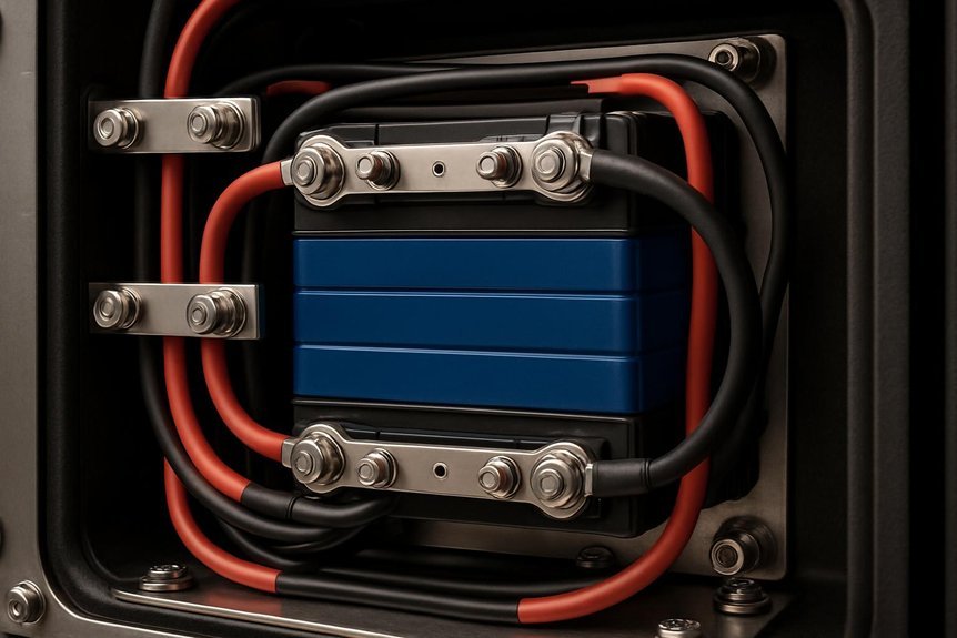
Wiring Fundamentals: Busbars, Conductor Sizes, and Fusing
When designing wiring for a deep cycle system, rigorous attention to busbars, conductor sizes, and fusing is essential to ensure safety, reliability, and optimal performance. We examine busbar sizing to minimize resistance, heat, and voltage drop, and we address common wiring misconceptions that lead to over- or under‑rating components. Conductor sizing follows standard ampacity charts, factoring in temperature, allowable voltage drop, and enclosure conditions. Fusing must protect conductors and components without introducing nuisance blows. We favor robust termination practices, secure mounting, and clear labeling to sustain system integrity.
- Busbar sizing and layout considerations
- Correct conductor sizing to prevent excessive heat
- Practical fusing strategy aligned with system currents
BMS Integration: Selecting and Wiring the Battery Management System
We’ll start by outlining the BMS types and how their architectures affect monitoring, safety, and scalability, so you can match a unit to your system’s needs. Next, we’ll cover wiring and sensor setup, including placement, communication protocols, and calibration to ensure accurate cell data and reliable protection. Finally, we’ll discuss protection and balancing strategies to maintain cell health, extend pack life, and prevent failures in routine operation.
BMS Types Overview
We begin by outlining the key BMS types and their core roles, so you can compare how each one handles cell balancing, protection, and communication with the rest of the system. We describe how passive balancing minimizes heat, while active balancing reallocates energy for efficiency. We contrast standalone BMS units, which centralize monitoring, with integrated BMS modules that embed protection and communications within the pack. We also consider cloud-connected or data-logging variants for diagnostics. bms types influence installation approach, reliability, and battery safety, guiding how we size conductors and fuse protection accordingly. A careful selection aligns balancing strategy, fault protection, and communication protocol with system demands.
- Passive, active, or integrated balancing approaches
- Standalone versus pack-integrated protection and data
- Communication interfaces and fault reporting considerations
Wiring And Sensors Setup
Wiring and sensors setup begins by selecting a BMS that matches the chosen balancing approach and protection strategy, then laying out the connections to cells, pack terminals, and auxiliary sensors. We proceed with a disciplined plan, identifying main harness routes and ensuring each connection reaches its designated contact without crossing high-current paths. Our approach emphasizes robust wire routing, minimizing exposure to vibration and heat, while preserving accessible diagnostic points. We document polarity, fuse placement, and shielded communication lines, ensuring compatibility with the battery pack’s cell arrangement. We verify sensor ports for temperature, voltage, and current, aligning them with the BMS input requirements. We test continuity, insulation integrity, and secure clamping to prevent movement. Throughout, we prioritize battery safety, maintain clean cable management, and confirm all signals reflect accurate real-time data.
Protection And Balancing Strategies
How should we choose a BMS that reliably balances cells and protects the pack, and how do we wire it to ensure accurate sensing and safe operation? We evaluate balancing strategy, overcurrent protection, and voltage limits, prioritizing cells with matched capacity and chemistry. We select a BMS with proper current rating, temperature sensing, and communication compatibility, avoiding ignored topics that could compromise reliability. Wiring must provide correct sense lines for each cell group, proper isolation, and reliable pack temperature feedback to prevent false trips. We integrate sense resistors, fuses, and proper polarity, verifying addressable channels and alarm outputs. We document guardrails to minimize unrelated factors during installation and commissioning, ensuring safe operation and traceable maintenance.
- Ensure per-cell balancing is active or passive as required
- Verify accurate voltage, current, and temperature sensing
- Map channels to the correct cell groups and alarms
Charging Requirements and Choosing the Right Charger
Understanding charging requirements and selecting the appropriate charger is essential for the longevity and safety of deep cycle lithium batteries. We guide you to match battery chemistry, capacity, and charging profiles to a capable charger with appropriate current limits. Our approach emphasizes correct CC/CV control, proper termination voltage, and temperature compensation features that protect cells during charging. Avoid nonsensical combinations of high current with limited wire gauges, which can cause voltage sag and heat buildup. We distinguish essential parameters from non essential topics, and we focus on practical, verifiable criteria rather than unrelated considerations. Choose chargers with certified safety features, accurate state-of-charge indicators, and documentation of input/output specifications. We recommend verifying compatibility with battery management systems, ensuring proper connector integrity, and maintaining a documented charging protocol for repeatable results.
Temperature, Ventilation, and Thermal Management Basics
Maintaining proper temperature, ventilation, and thermal management is integral to the long-term health of deep cycle lithium batteries and to safe system operation. We address these fundamentals with a disciplined approach that prioritizes data-driven decisions, sensor feedback, and conservative design margins. Temperature engineering guides cooling and heating strategies to keep cells within optimal ranges, while ventilation modeling informs air exchange rates and enclosure integrity. Together, these practices minimize thermal runaway risk, mitigate degradation, and sustain performance under varying loads. Accurate monitoring supports proactive maintenance and rapid fault isolation, ensuring system reliability over life cycles.
- Ensure clearly defined cooling pathways and avoid airflow obstructions
- Validate venting calculations with modeled and empirical data
- Schedule regular sensor calibration and thermal performance reviews
System Layouts for Campers, Boats, and Off-Grid Use
System layouts for campers, boats, and off-grid installations require a disciplined approach to ensure safety, reliability, and efficiency. We present clear, structured configurations that optimize space, wiring routes, and cooling while minimizing loss. We align battery placement with weight distribution, accessible fuses, and ventilation pathways, avoiding clutter and interference. Our layouts emphasize modular harnessing, secure mounting, and serviceability, so maintenance remains straightforward. We address supply segregation, battery monitoring, and charge controller siting to prevent cross-coupling in compact areas. To illustrate, consider the following imagery:
| Zone A | Zone B |
|---|---|
| Central cabinet with dual DC disconnects | Exterior ballast box with vented housing |
Note: unrelated topic and off grid fiction inform illustrative framing but do not replace engineering specifics.
Installation Dos and Don’ts: Common Pitfalls to Avoid
Are you aware of the most common installation pitfalls that can compromise safety and performance in a deep cycle lithium battery system? We outline practical guidelines to prevent failure, emphasizing disciplined wiring, secure mounting, and correct charging practices. By avoiding unnecessary complexity, we treat each step as a concrete action rather than an abstract concept, focusing on reliability and safety. We also acknowledge an unrelated topic that occasionally distracts teams, and we recommend eliminating such diversions from critical workstreams to preserve outcome quality. Precision in labeling, torqueing, and enclosure ventilation reduces risk, minimizes thermal risk, and supports system longevity. By adhering to these dos and don’ts, you preserve performance without increasing maintenance overhead.
Prioritize clean, tight connections, secure mounting with ventilation, and precise labeling to maximize safety and longevity.
- Verify connections are clean, tight, and torque-appropriate.
- Mount securely with proper isolation and ventilation.
- Use compatible, labeled fusing and clear cable routing.
Maintenance and Monitoring for Long-Term Longevity
How can we sustain optimal performance over time? We approach maintenance and monitoring as essential, not optional, activities. Regular checks should verify cell balance, connector integrity, and enclosure cleanliness, with any deviations documented and addressed promptly. We establish a disciplined maintenance scheduling routine that aligns with operating cycles and manufacturer recommendations, ensuring consistent attention without interrupting critical power loads. Temperature, voltage, and state-of-charge trends are tracked to anticipate capacity fade and mitigate thermal stress. We maintain a precise inventory tracking system to monitor component lifecycles, replacement parts, and warranty windows, reducing downtime and cost. Documentation updates accompany each service, enabling reproducible results and accountability. Together, these practices extend longevity, preserve safety, and enhance system reliability for demanding applications.
Frequently Asked Questions
How Does Depth of Discharge Affect Cycle Life in Practice?
Depth of discharge directly shapes cycle life: higher DoD reduces cycles more quickly, while shallower DoD extends life. We project long-term reliability by limiting daily DoD and managing charge rates, temperatures, and state-of-health expectations for better cycle life.
What Is the Best Installer Safety Checklist Before Hookup?
Before hookup, we insist on safe handling and PPE requirements, plus welding isolation; we compare caution to speed, ensuring rigor. We, readers, follow our installer safety checklist, detailing steps, verifying connections, securing containment, and confirming system integrity.
Can Lifepo4 Tolerate Occasional Overcharge Without Damage?
We can tolerate occasional overcharge in LiFePO4 without damage, but it isn’t recommended and should be avoided. We’ll monitor, balance, and protect cells, avoiding unrelated topic, irrelevant discussion, to maintain safety and longevity for your system.
How to Size a Solar Array for Mixed Load Days?
To size a solar array accurately for mixed load days, we calculate daily energy needs, factor efficiencies, then select panels to meet peak production. We, consequently, determine derates, battery discharge limits, and system loss margins for reliability.
What Are Signs of Deteriorating Battery Health Indicators?
Signs of deterioration include reduced capacity, increased internal resistance, and faster voltage sag. Our battery aging indicators show shortened cycle life, more frequent recharges, and temperature anomalies; we monitor diligently and advise proactive maintenance to preserve performance.
Conclusion
We close with clarity and care: future-proof your facility by following fundamental, fault-averse fundamentals. Thorough planning, tight tolerances, temperature-tuned tuning, and thoughtful, safe wiring foster fault-free functionality. Commitment to concise compliance, careful commissioning, and consistent maintenance maximizes reliability, longevity, and load-bearing life. We emphasize meticulous mounting, mindful monitoring, and methodical documentation. Let’s lock in disciplined design, diligent deployment, durable durability, delivering dependable, danger-free daily operation and enduring, efficient energy everywhere.

